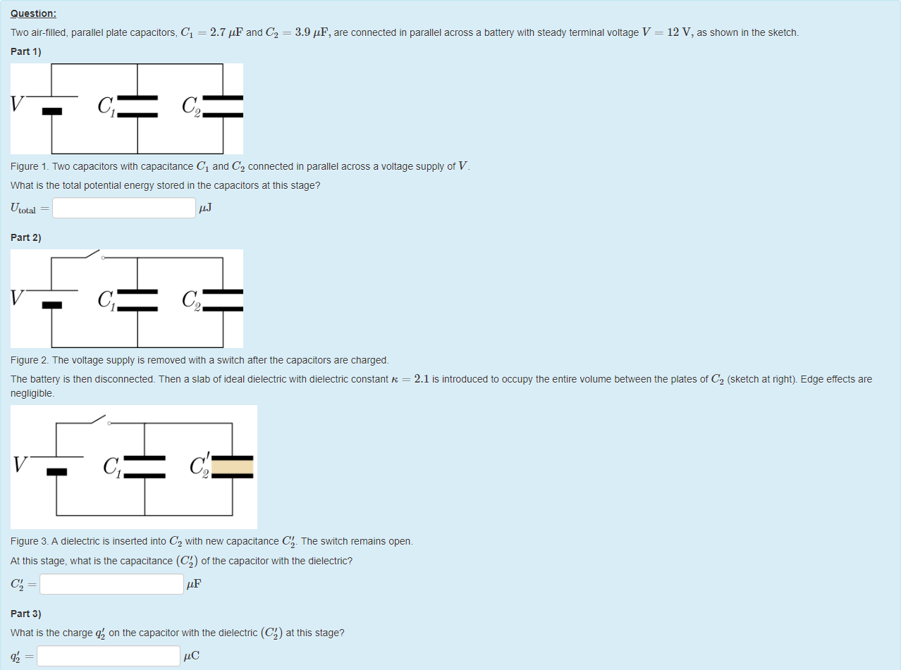
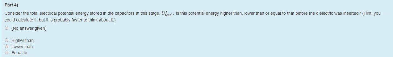
Two air-filled, parallel plate capacitors, C1=2.7 μF and C2=3.9 μF, are connected in parallel across a battery with steady terminal voltage V=12 V, as shown in the sketch.

Sunday, 26 August 2018

12:55 AM

Machine generated alternative text:
Question: 
Two air-filled, parallel plate capacitors, Cl = 
part 1) 
2.7 = 
3.9 'IF, are connected in parallel across a battery with steady terminal voltage V 
12 V, as shown in the sketch. 
Figure 1 _ Two capacitors witn capacitance Cl and C2 connected in parallel across a voltage supply ot V 
What is the total potential energy stored in the capacitors at this stage? 
Utotal 
part 2) 
Figure 2. The voltage supply is removed with a switch after the capacitors are charged. 
The battery is then disconnected. Then a slab ot ideal dielectric with dielectric constant K = 2.1 is introduced to occupy the entire volume between the plates of C2 (sketch at right). Edge etfects are 
negligible. 
Figure 3. A dielectric is inserted into C2 witn new capacitance C' _ The switch remains open 
At this stage, what is the capacitance (CO of the capacitor with the dielectric? 
part 3) 
What is the charge q'2 on the capacitor witn the dielectric (CO at this stage?

Machine generated alternative text:
Part 4) 
Consider the total electrical potential energy stored in the capacitors at this stage, [J(otal. Is this potential energy higher than, lower than or equal to that before the dielectric was inserted? (Hint: you 
could calculate it, but it is probably taster to think about it.) 
O 
O 
O 
O 
(No answer given) 
Higher than 
Lower than 
Equal to


Machine generated alternative text:
Feedback tor Part 1) 
Figure 1 _ Two capacitors witn capacitance Cl and C2 connected in parallel across a voltage supply ot V 
Marks for this submissiom 0.00/0.25. This submission attracted a penalty of 0.08. 
Feedback tor Part 2) 
Instead of vacuum (K = 1), the second capacitor has K > 1 so C' = KC . 
Figure 1 _ Two capacitors witn capacitance Cl and C2 connected in parallel across a voltage supply ot V 
Figure 2 The voltage supply is removed with a switch after the capacitors are charged. 
Figure 3. A dielectric is inserted into C2 witn new capacitance C' The switch remains open. 
Marks for this submissiom 000/0 25 This submission attracted a penalty of 0.08. 
} (Cl + C2)V2


Machine generated alternative text:
Feedback tor Part 3) 
From the definition of capacitance, qi = CIV and = C2V. From this and conservation of charge, the total charge on both capacitors is always (Cl + C2)V, so for the final charges 
= (Cl C2)V. (1) 
The two capacitors are once again in parallel, so their voltages are again equal at 
SO qi = 
c; 
KC2 q2 • 
Substituting into (1) gives 
+ 1) = (Cl + C2)V 
KC2 
(Cl+C2) V OR (Cl+C2) C V. 
+1 
Figure 1. Two capacitors with capacitance Cl and C2 connected in parallel across a voltage supply of V. 
Figure 2. The voltage supply is removed with a switch after the capacitors are charged. 
Figure 3. A dielectric is inserted into C2 witn new capacitance C'. The switch remains open.


Machine generated alternative text:
Feedback tor Part 4) 
You have correctly answered this part 
Marks for this submissiom 0.25/0.25. 
A correct answer is 480, which can be typed in as follows: 
488 
A correct answer is 8.2, which can be typed in as follows: 
A correct answer is 60, which can be typed in as follows: 
A correct answer is 2


Created with Microsoft OneNote 2016.