Step Response of RC Circuit

Monday, 27 August 2018

12:31 PM

The step response is the response of the circuit due to a sudden change in DC voltage or current.

  • It is the circuit behaviour when the input/excitation is the step function
  • We can model this behaviour with a switch opened or closed at


A unit step function, denoted by  is:

 for negative values of time

 or positive values of time


It serves as a good approximation to switching signals representing a sudden change in voltage or current


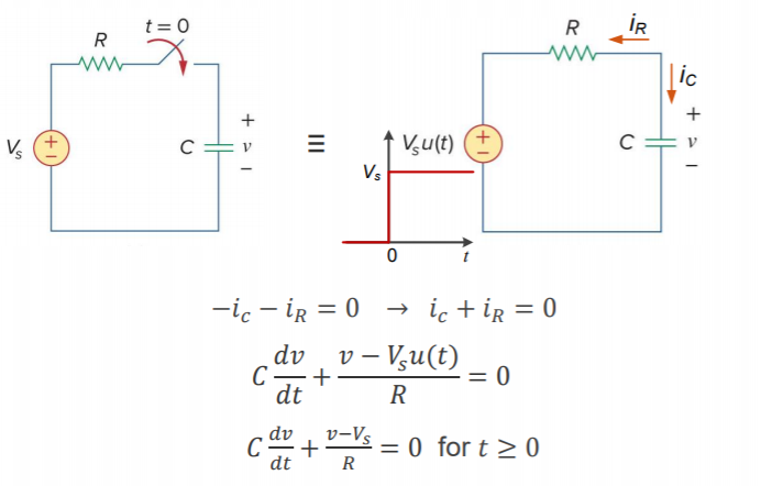
To analyse the step response, we can use KCL at the node between the resistor and capacitor

Machine generated alternative text:
ic 
dt 
dv 
dt 
Vsu(t) 
v - vsu(t) 
v-vs = 0 for t 2 0


Machine generated alternative text:
Solve differential equation: 
dv v—V 
Rearrange: 
S = O, t 20 
dt 
dv 
-1 
(V ¯ Vs) 
—1 
Separate: 
Integrate: 
Solve for v(t): 
Apply initial conditions 
V(0) = vs = vo 
1 
dv = 
dv = 
dt 
RC 
v(t) 
—t 
In(v — Vs) ¯ 
v(t) — Vs = eRC 
—t 
= Vs + (vo — Vs)eFC , t 0


Machine generated alternative text:
• No need to derive the differential equation solution every time, just use the result. 
• The result shows that the voltage response of the RC circuit will change from 
the initial Vo to the value of Vs in an exponential manner. 
Depending on the value of initial conditions Vo and voltage source Vs, the capacitor can 
be charged or discharged. 
o, 
v(t) = 
Vs + (Vo — Vs)e RC, 
v(t) 
Vsu(t) 
v(t)


Machine generated alternative text:
• The concept of time constant also applies to step response. 
The time constant of a circuit is the time required for the response to decay 
to l/e (or 36.8%) of its initial value or to increase to 1 — l/e (or 63.2%) of its 
final value. It is denoted by T. 
• After 5 time constants (5r), the capacitors is again considered as open circuit 
as its voltage is no longer changing. 
0.632Vs — 
Vs > Vo 
v(t) = 
o, 
Vs + (Vo — Vs)e-F,


Machine generated alternative text:
• The step response has two components: 
v(t) = vs + — vs)eT, t > o 
v(t) = Voe-F + Vs(l — e¯7), t > O 
Natural 
response 
Forced 
response 
Due to stored Due to 
Independent 
energy 
sources 
Complete response = natural response + forced response 
v(t) = vn(t) + vr(t), t > O 
This can be viewed as superposition principle in RC circuits for two sources of energy powering the circuit: 
1. Initial conditions (stored energy) 
2. Independent sources


Machine generated alternative text:
• From another perspective: 
The transient response is the circuit's temporary response that will die out with time. 
The steady-state response is the behaviour of the circuit a long time after an 
external input/excitation is applied (after 5 time constants, 5T). 
v(t) = vs + - vs)e-i, t > O 
Steady-state Transient 
response response 
Permanent Temporary 
part 
part 
Complete response = transient response + steady-state response 
v(t) = vt(t) + vss(t), t > O


Machine generated alternative text:
Step response of RC circuit 
• More specifically: 
1. First stage of steady-state 
There has been no change in 
the circuit for a long time and 
the capacitor is an open circuit 
with v(O) = Vo. 
2. Transient stage (O < t < 5T): 
The capacitor's voltage changes 
exponentially. 
3. Second stage of steady- 
v(t) 
First stage of Transient stage 
state (t > 5T): 
steady-state 
Second stage 
of steady-state 
The capacitor's voltage reaches 
its final value or steady-state 
value and becomes open 
circuit again with v(t) = Vs 
when t co or v(Ø) = Vs 
v(t) = vs + (Vo — vs)eT, 
v(t) = v(oo) + [v(O) — t > O


Machine generated alternative text:
Step response of (complex) RC circuit 
• The step response solution has been derived for a circuit with one single 
capacitor and resistor. 
• It is possible to find the voltage across a capacitor in a complicated circuit with 
multiple resistors, switches, independent and dependent sources by replacing 
the circuit with its Thevenin equivalent circuit. 
Resistive 
circuit with a 
switch 
— or -2>5 
RTh 
b 
VTh 
c


Machine generated alternative text:
Step response of RC circuit 
• Follow these steps to find step response of RC circuits: 
1. 
Find the initial voltage v(O) at t = O across the capacitor before any 
changes in the circuit (t < O). 
The capacitor is assumed to be an open circuit. 
2. 
Find the final voltage v(co) or VTh a, at t -+ 00 across the capacitor after 
the changes in the circuit (t 2 0). 
3. 
Find the time constant T = RTh coc after the changes in the circuit 
RTh_00 is Thevenin equivalent resistance after the changes (t 0). 
4. Calculate the voltage across the capacitor as: 
v(t) = v(co) + [v(O) — 
Find any other circuit variable using the capacitor's voltage. 
5. 
Note: A switch which opens or closes can remove part of the circuit or add something to it.


Machine generated alternative text:
Time shift in step response of RC circuit 
• Note that if the switch changes position at time t = to instead oft = O, there 
is a time delay in the response which can be expressed as time shift in the 
equation. 
This method can be used for multiple switching at different times. 
—(t—to) 
v(t) = v(oo) + [v(to) — T


Created with Microsoft OneNote 2016.