Physical Layer Fundamentals 2
Contents
Detailed Notes: detailed_w2_lecture_notes.pdf
Antennas
Converts electrical energy into EM waves, as well as EM waves to electrical energy
Same antenna for both transmission and reception
Types of Antennas
- Omni-directional - All directions
- Directional - Most power in the desired direction
- Isotropic - Radiate in all directions equally
Antenna Gain
- Power at a particular point / Power with an isotropic antenna
- Expressed in dBi (Decibel relative to isotropic)
- i.e. 17 dBi antenna
- $ 17 = 10 log_{10} (P/P_{iso}) $
- $ P/P_{iso} = 10^{1.7} = 50.12 $
Antenna Length
- Antennas are designed to transmit or receive a specific frequency band
- End-to-end antenna length = 1/2 wavelength
- Electrons can travel back and forth in one cycle
- For dipole (two rods), each rod is 1/4 wavelength
- Manufacturers use magic/electronics to use the same antenna for both 2.4 GHz and 5 GHz
Reflection, Deflection and Scattering
- Reflection - wave bounces off
- Diffraction - Wave hits a corner, deflects at obtuse angles
- Scattering - If a wave hits a smaller object, it will split in several direction
Path Loss
- Power lost during transmission
- Path loss = $ P_T - P_R $
- Need to estimate path loss to design wireless links
Frii's Path Loss Model
For free-space (no reflections)
Frequency Dependent
$ P_R = P_T G_T G_R (\frac{\lambda}{4 \pi d})^2 = P_T G_T G_R (\frac{c}{4 \pi d f})^2 $
- $ G_T $ = Transmit antenna gain
- $ G_R $ = Receive antenna gain
For isotropic antennas, $ G_T = G_R = 1 $ so $ P_R = P_T (\frac{\lambda}{4 \pi d})^2 = P_T (\frac{c}{4 \pi d f})^2 $
The higher the frequency, the greater the path loss at a fixed distance
Logarithmic version
- $ 20\ log_{10} (\frac{4 \pi d}{\lambda}) = 20\ log_{10} (\frac{4 \pi d f}{c}) = 20\ log_{10}(d) + 20\ log_{10}(f) - 147.55 $
- Maximum distance
- Rearrange the formula to get $ d $
- $ d = \frac{c}{4 \pi f} \sqrt{P_T / P_R} $
Receiver Sensitivity
The received power (Received Signal Strength - RSS) has to be greater than a threshold in order to correctly decode information (with low error probability)
- Depends on channel bandwidth, receiver noise, and temperature
- Larger the bandwidth - larger the minimum power
- Larger the receiver noise - larger the minimum power
Multipath
Due to reflections, diffractions and scattering, multiple copies of the same signal may be received at different times.
The Line of Sight (LOS) signal reaches the receiver first, followed by the Non Line of Sight signals.
Multipath can be good, as it allows NLOS communication.
However, it can also be bad...
Inter-Symbol Interference (ISI)
Due to the multipath effect, received signals may interfere with each other.
Multipath pulses will generally have less power, so even if some multipath artifacts occur, if their power is not sufficient enough, it won't cause noticeable interference
Delay Spread
The duration that a signal is effectively received for (due to multipath effects).
Delay spread = time between the first LOS and last NLOS signal.
2-Ray Path Loss Model
- Model is independent of frequency
$ P_R = P_T G_T G_R (\frac{h_T h_R}{d^2})^2 $
$ 40 log_{10}(d) - 20 log_{10}(h_T h_R) $ (Unit gain antenna)
Model only works when devices are separated by at least $ d_{break} = 4 h_T h_R / \lambda $ (far field)
Path Loss Exponent
Regardless of the model, the path loss is modelled by $ PL(dB) = 10 log_{10} (d^n) + C = 10 \times n \times log_{10} (d) + C $
Small Scale Fading
Phase change occurs due receiving signals at different times (due to multipath).
Fading - small movements can significantly affect the amplitude.
Large Scale Shadowing
Shadowing - sustained signal loss over large distances (i.e blocked by a building)
MIMO - Multiple Input Multiple Output
Multiple antennas for transmitter and receiver
Allows for multiple paths which won't interfere - space antennas $ > \lambda / 2 $
- Improve signal quality and data rate
Single antenna devices can still benefit from MIMO units
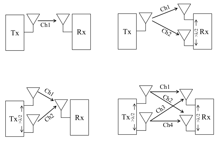
- Spatial Diversity - Improve reliability
- Spatial Multiplexity - Improve data rate
- Beamforming - Increase coverage and signal strength in a particular direction
Spatial Diversity
Send the same data over all of the paths (redundancy). The strongest signal will be processed.
Number of paths = number of transmit antennas $ \times $ number of receive antennas
Spatial Multiplexing
Different bits of the data are sent over different channels (Increase data rate)
Degrees of freedom = $ min(N_T, N_R) $
Beam Forming
Phase shift some of the signals so that they constructively interfere, and increase the SNR and range!
Virtual directional antennas.
Orthogonal Frequency Division Multiplexing - OFDM
The next frequency band begins to transmit when the previous transmission reaches its peak amplitude.
Multiple smaller channels is better than a single larger channel
- Better at adapting at a finer resolution
- Each channel can use a different modulation technique / coding method
- Some atmospheric noise only affects certain frequencies (narrow-band interference), so those smaller frequency ranges can be adjusted independently of other channels
Some channels can be used as 'pilot subcarriers' for channel estimation
Design Consideration
- Subcarrier spacing = frequency bandwidth / number of subcarriers
- Large number of carriers -> smaller data rate per carrier -> larger symbol symbol duration -> less inter-symbol interference
- Reduced subcarrier spacing -> Increased ICI due to doppler spread.
Orthogonal Frequency Division Multiple Access - OFDMA
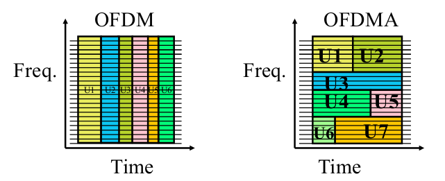
2D Scheduling
Each user uses a subset of subcarriers for a few time slots
Users are given different frequencies at different times
Effect of Frequency
- Higher frequencies have higher attenuation
- Higher frequencies need a smaller antenna
- Higher frequencies are affected more by weather
- Higher frequencies have more bandwidth and data rate
- Higher frequencies allow more frequency reuse (they drop off faster, so more can be used in a large space)
- Lower frequencies have longer reach
- Longer cell radius
- Good for rural area
- Smaller number of towers needed
- Less power draw (Longer battery life)
- Low frequencies require larger antennas, and need to be spaced further apart
- Lower frequencies -> smaller channel width
- Need more aggressive modulation to get a higher data rate
- Doppler shift