Network Layer - Data Plane
Contents
IP Packet Structure
Version, header length, type, length, id, flags, fragment offset, ttl value, protocol, checksum, source address, destination address, options, payload
- Version (4 bits) - IP version - usually 4 for IPv4
- Header length (4 bits) - Number of 32-bit words in the header
- Usually
5(for 5 x 32bit words = 5 * 4 bytes = 20 bytes)
- Usually
- Type of Service - TOS (8 bits) - Special flags (i.e. low latency audio)
- Total length (16 bits) - number of bytes in the packet (max 65535)
- TTL (8 bits) - Remaining hops before the packet is discarded
- Set to 255 (0xFF) initially
- Decreases by one each time the packet is forwarded
- Discarded when the TTL is 0
- Protocol (8 bits) - Identifies the Transport protocol - i.e. TCP/UDP/ICMP/etc
TTL
Packets may be forwarded in a circle, and never reach their destination.
To stop a packet from being constantly circulated; the packet has a Time To Live value, which limits the number of forwards it may take.
Header Corruption
A checksum is used to verify that the header data has not been corrupted during transmission.
If the checksum is invalid, the packet is discarded.
Only the header is checked, as the transport layer protocol has its own checksum
Fragmentation
Each layer has its own maximum packet size. Encapsulated packets are split into chunks of these maximum sizes, allowing them to be transmitted over the network. This is known as fragmentation.
i.e. The Ethernet protocol has an MTU (maximum transmission unit) size of 1500 bytes - so any TCP packet larger than 1500 bytes will be split into several fragments
Fragments are reassembled at the destination, and are grouped together by the IP header bits (ie id, and fragmentation offset)
Fragments
Fragments will have an id, fragmentation offset value and a more fragments flag to indicate the group and metadata of the packet.
Fragments may be re-fragmented as they go down the OSI layer stack.
MTU Discovery
A host will send a large packet with the Do Not Fragment (DF) flag.
Routers along the network will attempt to route the packet.
If they cannot handle the packet size, they will drop the packet, and send an ICMP message to the host with their maximum supported size.
IP Addresses
- IP Address: 32 bit value to identify a host to the router interface
- Interface - Connection between host/router and a physical link
Network Masks
Used to indicate how many higher order bits are used for the network identification, and how many low order bits are used for the host identification
Network Address
The network address is a special address where all of the host bits are 0
Broadcast Address
The broadcast address is a special host address, where all the host bits are 0
Network Classes (old)
- Class A - 8 bits | 24 bits
- Class B - 16 bits | 16 bits
- Class C - 24 bits | 8 bits
- Class D - Multicast
Class D - Reserved
Identify by how many 1s are consecutive from the very start
Subnets
Divides a network internally into smaller network.
This is done by splitting the host bits into subnet bits and the remaining host bits
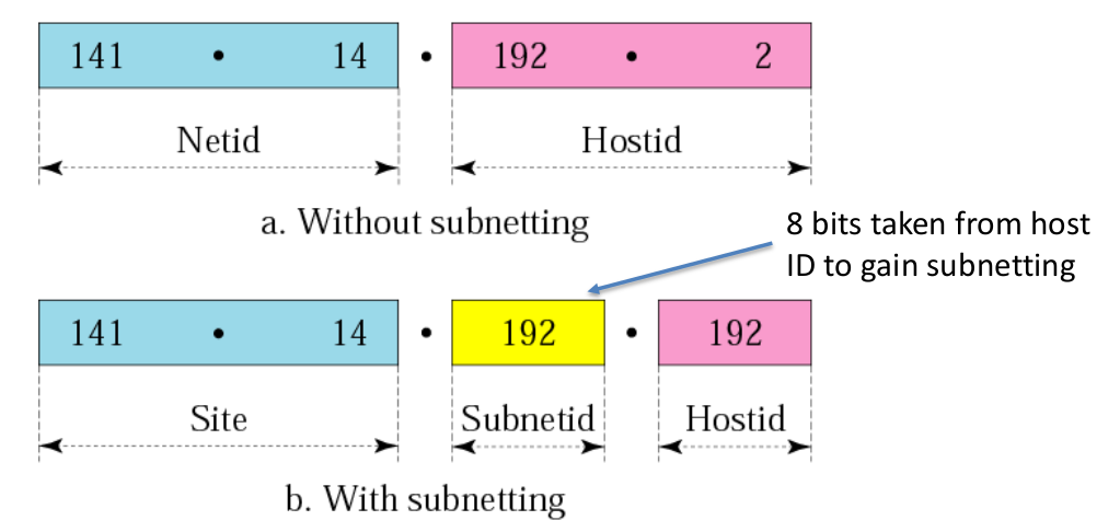
- Transparent - A device outside of this network won’t see any difference
CIDR - Classless Inter-Domain Routing
Format a.b.c.d/x where x is the number of network bits
Allocation of IP Addressess
Block Allocation
An organisation becomes a subnet of the ISP’s network
Dynamic Host Configuration Protocol - DHCP
DHCP Servers that allocate IP address to clients.
- Clients send
DHCP Discover- To find DHCP servers - Servers send
DHCP Offer- To advertise server - Clients send
DHCP Request- To request for an IP - Servers send
DHCP Acknowledgement- To assign an IP
DHCP Servers can also supply more information, such as the suggested DNS server, subnet mask, and gateway IP (first hop for client).
The DHCP protocol uses UDP Port 67 (Server) and 68 (Client). The MAC address of the client is used to identify themselves.
Hierarchical addressing: route aggregation
An advertised route with a more specific route (more network bits than host bits // longest prefix matching) will receive the forward
Network Address Translation (NAT)
A router is often the only device that faces the internet, with client devices connected locally.
As a result, devices on the internet cannot directly connect to the client devices.
Instead, packets are sent to the router, which will perform Network Address Translation to forward the packet to the client, and also to forward the packets from the client.
With this, the source and destination IPs and Ports are remapped.
- Outgoing datagrams -> Replace source IP and port with NAT IP and port
- Incoming datagrams -> Replace NAT IP and port with Source IP and Port
i.e. A NAT may translate 110.20.160.140:1701 to 192.168.1.80:80, and 11.20.160.140:1702 to 192.168.1.58:80.
Consequently, changes to the internal network will not be seen by external devices.
Static Configuration
i.e. Port Forwarding
Dynamic Configuration - UPnP
NATs will learn the public IP and dynamically add/remove ports
NAT is Controversial
- Violates design of a router - Process up to Layer 3 and not look at Layer 4 (IP)
- Application designs must take into account the possible existence of NAT
- P2P
- Holepunching
… meh