I/O Management
Contents
Unifying the interface and communication of Input Output devices
Device Drivers
Software interface to hardware (so we don't need to spin a motor to access files on a hard drive)
They translate requests from device-independent standard interfaces (open, close, read, write) to appropriate commands for the particular hardware. They also manage the initalisation and safe shutdown of hardware.
They come in two categories:
- Block devices - Operate with a block of data
- Character / Stream devices - Operate byte by byte
Drivers are thread-safe - meaning that they can be called by multiple programs, but service them in a synchronous manner
Interfacing between the Kernel and the Driver
Kernels expose a set of standard protocols and functionality (ie open, close, read, write) that drivers would extend to suit their needs.
This allows driver code to change without breaking the kernel, and kernel code to change without breaking the driver (provided they are written right, and do not violate the standard protocol).
Accessing IO
Separate IO and Memory Addresses
IO controller registers appear as IO ports, and are accessed with special IO instructions
Memory Mapped IO
Controller registers appear as memory addresses.
Normal load and store instructions can be used to access the controller registers
Bus Architecture
| Single Bus Architecture | Dual Bus Architecture |
|---|---|
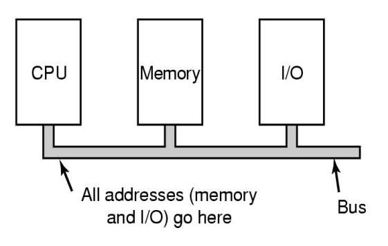 | 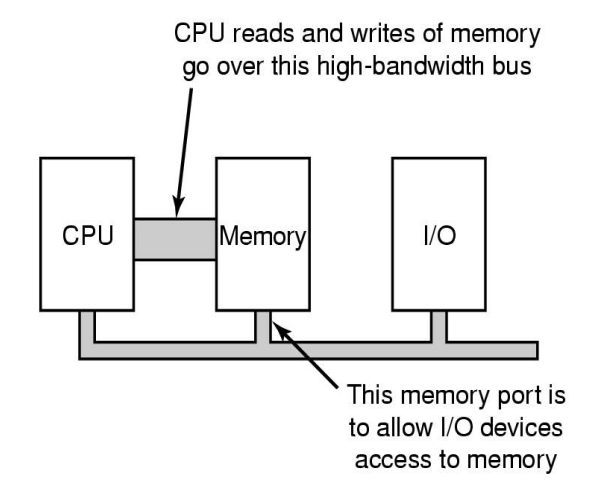 |
Waiting for Data
Waiting
The program continuously polls the IO status register to see if the IO device is ready to transmit data
Device Interrupts
Devices are connected to an Interrupt Controller (through IO bus).
When the device is ready, the interrupt controller sends the CPU an interrupt signal.
This method however increases the processor time, as all interrupt data is passed through the processor.
Direct Memory Access
With a DMA controller (either in the device, or external) - devices are able to access the memory without needing to involve the CPU. When a task is complete, the CPU is sent an interrupt signal, in the event that the CPU needs to do something.
Using DMA, the CPU is only involved during the start and end of the memory access; saving CPU time.
Less context switches and user/kernel mode switches will occur
Interrupt Handlers
Interrupt handlers (aka Interrupt Service Routines) are program instructions that are called when their respective interrupt signal is raised. They can be executed at almost any time, and generally has no context on what process was previous running.
ISRs should run quickly and shortly; meaning that they should not require (m)any IO operation
Top and Bottom Halves
Execution of the ISR is split into two halves.
- The Top half is the main entry point of the ISR, and controls the operation of the Bottom half
- The Bottom half performs the main program work; and is not allowed to do any blocking operations
This lowers the interrupt latency
Buffering and Data Rates
Between different devices and controllers, they may be operating at different data rates.
When communicating between each other, these different data rates will mean that one device will transmit/receive data faster than the other.
Buffering aims to fix this 'clock' issue by creating a memory space where incoming data comes in until it fills.
When filled, all of the contents of that buffer is passed onto the device/process.
This is more efficient, as the device/process will not have to constantly keep checking for enough data.
And only a single system (and wakeup and block) call is needed.
Buffering does induce latency, as there is delay from waiting for data to fill, and for data to copy from the buffer into the destination location
User Buffering
If the buffer is paged to the disk; data could be lost, or deadlocks may exist if there is limited memory available.
Single Buffer
A buffer is stored in the system memory. When filled, the buffer is copied into the user memory.
- Block oriented - Input transfers
- User process can process one block of data whilst the next block is read in
- Swapping can occur since input is taking place in system memory
- OS keeps track of which system buffers are assigned to which user process
Buffering Speed Up
T- Transfer time for a block from deviceC- Computation time to process a blockM- Time to copy kernel buffer to a user buffer
= (T+C) / (MAX(T,C) + M)
- If the buffer fills and there is still more incoming data, data may be lost
- Bounded-buffer Producer-Consumer issue
Double Buffer
Two system buffers are used. When one is filled, new data enters the second buffer whilst the first buffer is read out.
Computation and memory copy can be done in transfer
= (T+C) / MAX(T,C+M)
Usually M << T so it is favourable to employ a double buffer.
- May not be good enough for bursty traffic (alot at a time, then none at all)
- Bounded-buffer Producer-Consumer issue
Circular Buffer
More than two buffers are used.
- Bounded-buffer Producer-Consumer issue