Implementation Technology
Contents
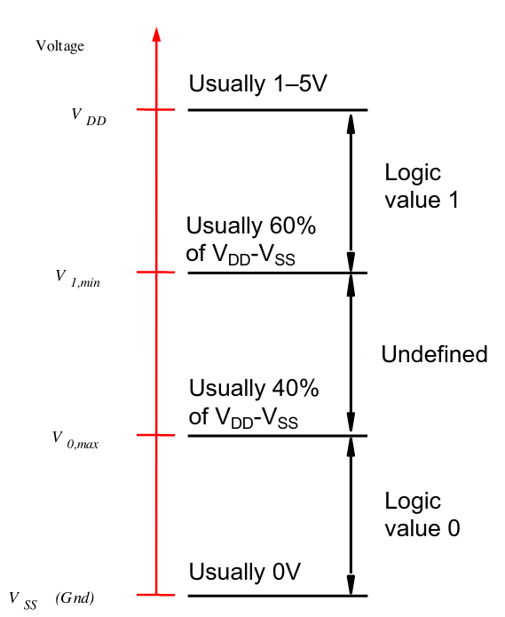
Logic values as voltage levels
Voltage (or even current) levels are often used to represent logic values.
In a positive logic system, low levels represent low values, and high levels represent high values (i.e 1)
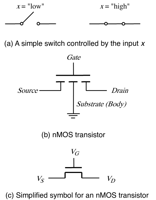
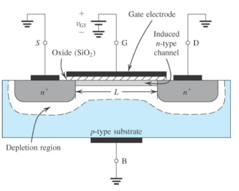
nMOS Transistors as Switches
Transistors are used either in cutoff mode or saturation mode
- nMOS - n-channel MOSFET
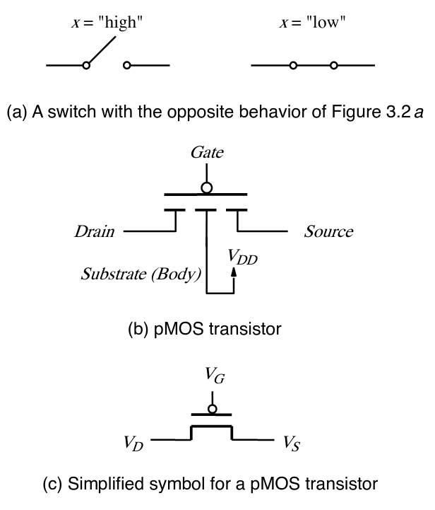
- pMOS - p-channel MOSFET
When $V_G > V_t$, $V_D ~= V_S$
- $V_t$ is the threshold voltage
pMOS
When $V_G < V_B$, $V_D = V_S$
Cutoff Mode ($V_{GS} < V_t$)
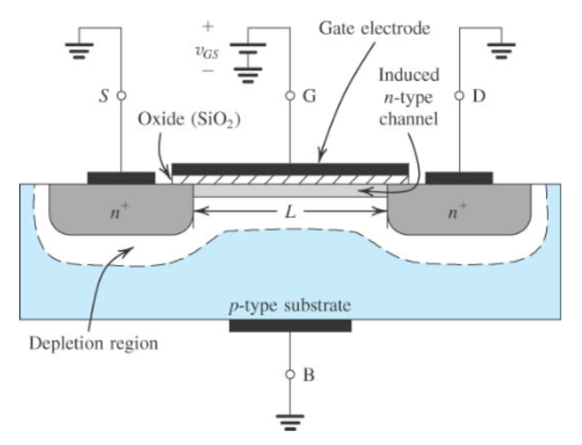
- Positive charge (from $V_{GS}$) builds up on the plate, which accumulates negative charge
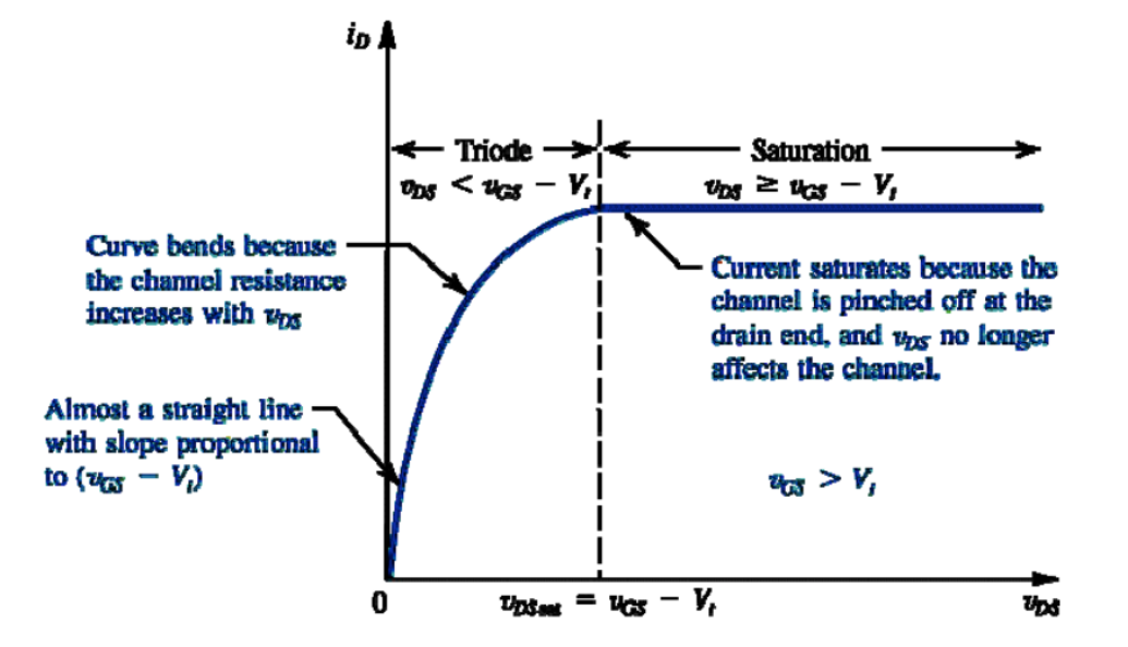
Cutoff Mode ($V_{GS} > V_t$ and $V_{DS} < V_{GS} - V_T$)
Pinchoff ($V_{DS} -> V_{GS} - V_t$)
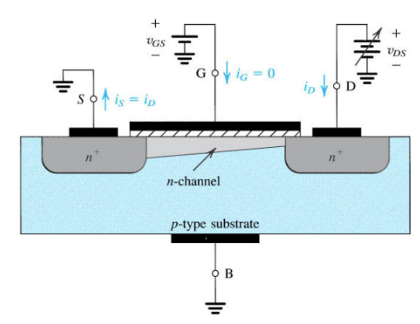
- When the voltage difference between the gate and drain is less than the difference between the gate and source.
- Resistance increases
Saturation Mode ($V_{DS} >= V_{GS} - V_t})
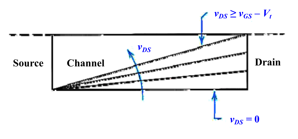
- Limited
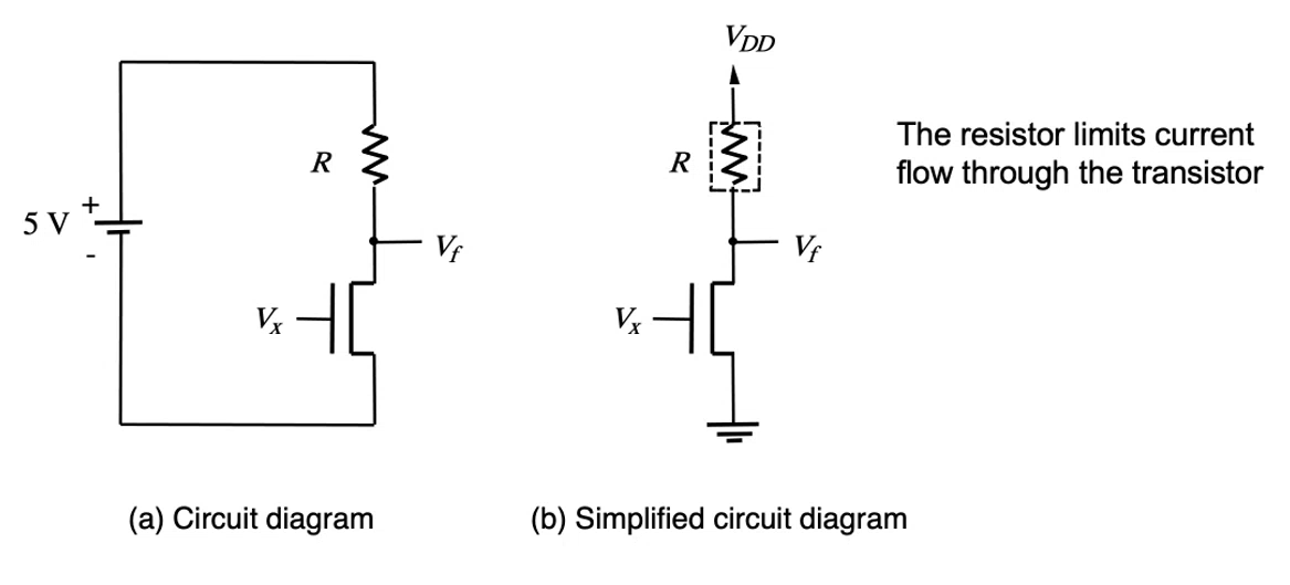
NOT gates using nMOS
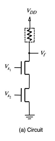
NAND gates using nMOS
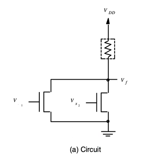
NOR gates using nMOS
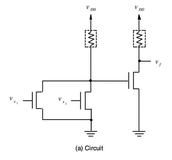
AND gates using nMOS
(NAND + NOT)

OR gate using nMOS
(NOR + NOT)
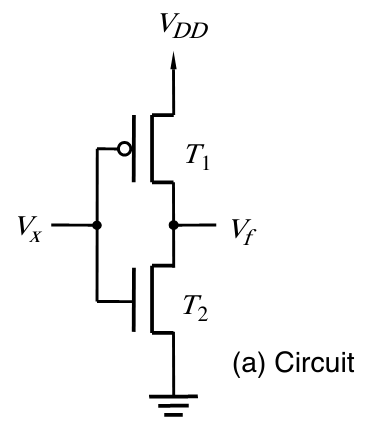
CMOS - Complementary MOS
- Equal number of transistors
- "duals" of each other
- PDN has nMOS in series
- PUN has pMOS in parallel
- Only one of the networks is active at any time.
- No longer require the current-limiting resistor.
- Almost no current flows - little to no power loss!
- There is however, leakage current
- Little current (dynamic power) is dissipated for the gate operation
- Proportional to the clock frequency and the square of the supply voltage $V_{DD}$
| NOT | NAND | NOR | AND |
|---|---|---|---|
 | 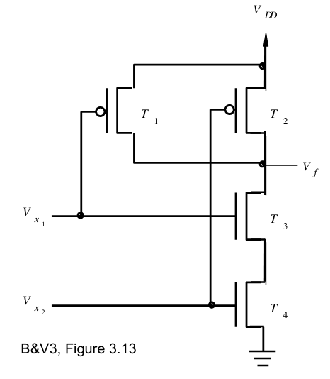 | 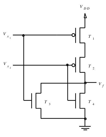 | 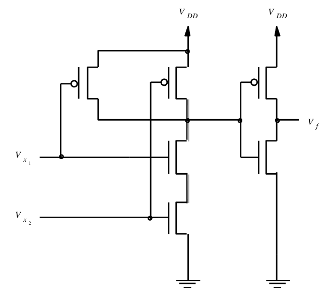 |
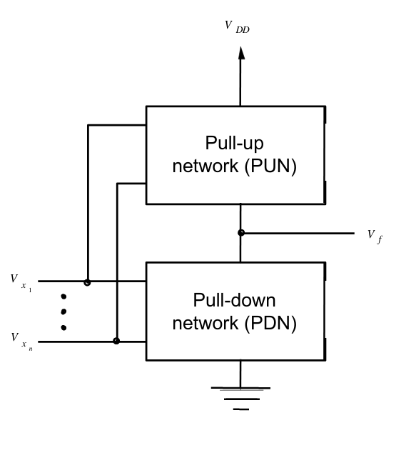
CMOS implementation for a generic network
Apply $f || \overline{f}$
Pull-up vs Pull-down
Pull-down is better
If pulling up to source voltage, there will be current flowing -> Power loss!
7400-series Chips
These ICs were released in the 1960 and contained few gates in the silicon substrate.
Eh
Programmable Logic Devices (PLD)
Programmable Logic Arrays (PLA)
AND and OR gates programmed through physical switches.
Programmable Array Logic (PAL)
PLAs but with the OR plane removed.
Selection of the OR gates are removed in favour of just implementing more OR gates
- Less expensive (less parts)
- Faster (less gates)
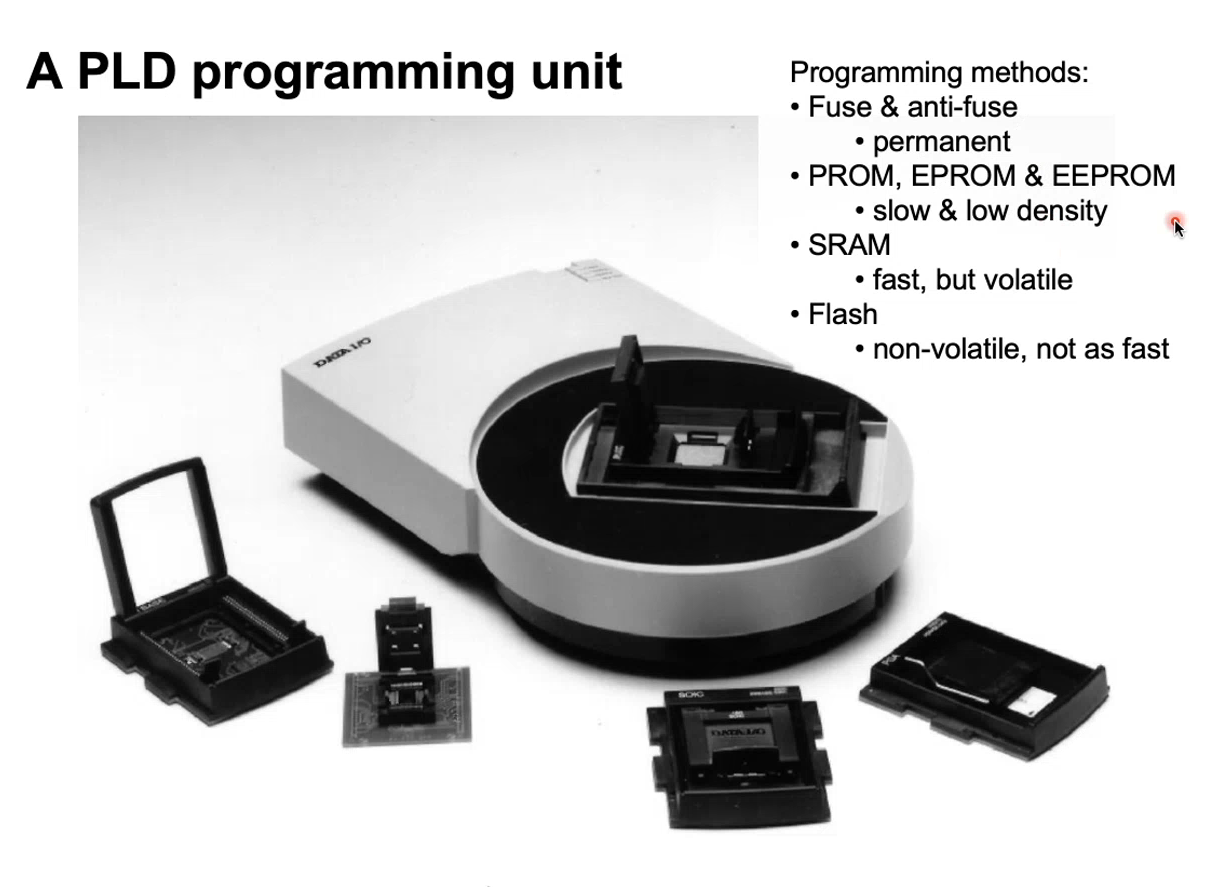
Programming Units
- XOR can be used as a NOT toggle!
- Expand input by cascading several multiplexers
- Use clocks to synchronise gate operations
- Flip-flops to hold values
- D-latch to hold asynchronous values