Arithmetic Circuits
Contents
Binary Addition
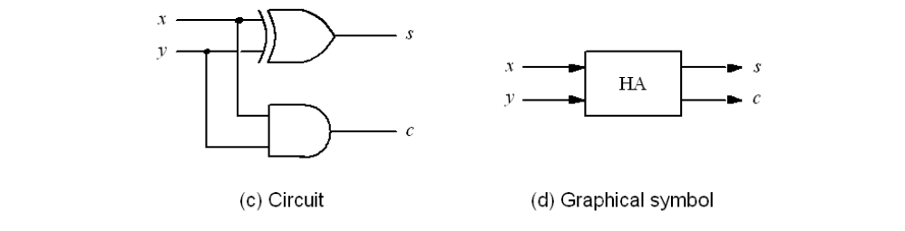
Half-Adder Circuit

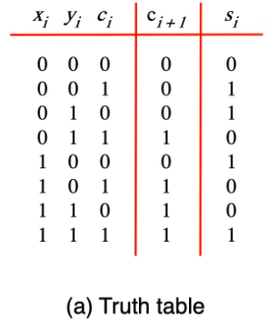
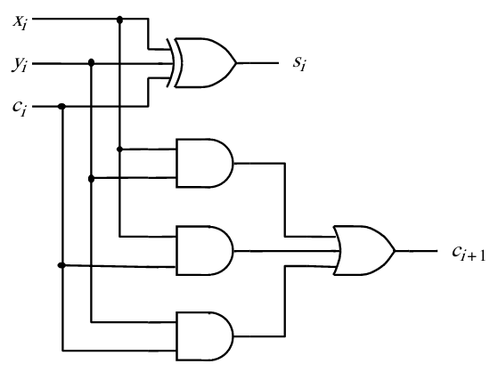
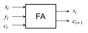
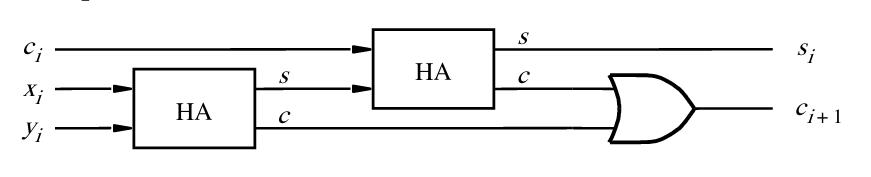
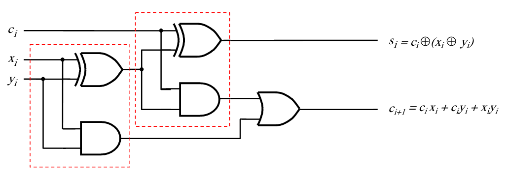
Full-Adder Circuit
Truth Table
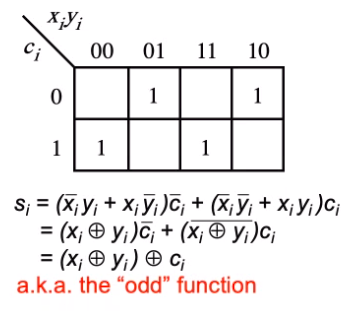
$s_i$ Karnaugh Map
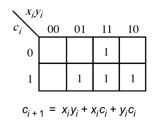
$c_{i+1}$ Karnaugh Map
Circuit
Symbol
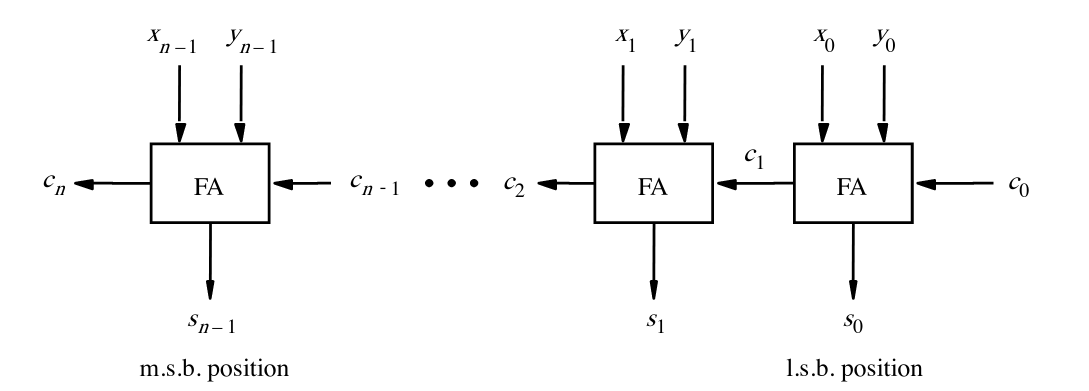
Decomposition
Example n-bit Ripply-Carry Adder
Subtraction
Subtraction is the addition of the two's complement
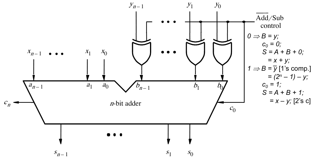
Adder/Subtractors using a Control Bit
- Using a XOR gate - can flip 0s to 1s
- A $\overline{Add}/Sub$ control signal also deals with the two's complement
- The speed of a circuit is limited by the longest delay along the paths through a circuit
- This path is called the 'critical path'
- The delay is known as the 'critical-path delay'
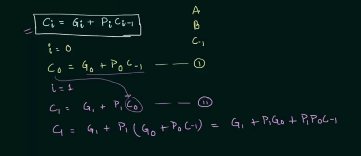
Fast Addition - Carry-lookahead addition
$c_{i+1} = x_i y_i + x_i c_i + y_i c_i$ can be rewritten as
$c_{i+1} = g_i + p_i + c_i$ where
$g_{i} = x_i y_i$ - carry generated when both bits are 1.
$p_i = x_i + y_i$ - carry propagated when either input bit is 1
This allows us to create a two-level AND-OR circuit
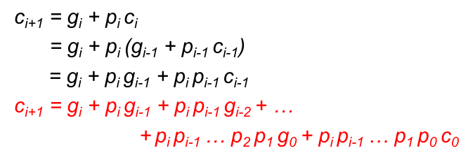
Notice that for {i+1}, the result for {i} is not needed!
Each stage can check if a carry has been generated, or if a carry has been propagated
- All carries are produced after 3 gate delays
- All sum bits are computed after 4 gate delays
- BUT each stage gets more and more complex
- Two more wires used per each stage
- 1 more AND gate with one more input per state
- One more input to the OR gate per stage
- It is wise to split a n-bit adder into smaller blocks
- i.e. Split a 32-bit adder into four 8-bit adders
- Could even do a lookahead of each group
- Using a carry-lookahead adder for 4x8=32bits uses a total of 8 gate delays
- A 32-bit ripple carry adder needs 64 gate delays
- Overflow occurs when $ \overline{c_{n-1}} c_{n} + c_{n-1} \overline{c_n} = c_{n-1} \oplus c_n $
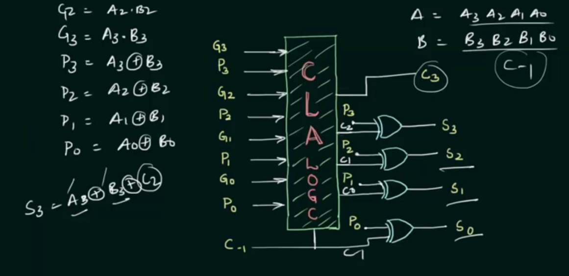
Since each bit is known, we can get the G (A*B) and P (A XOR B) values by having those gates for each pair of bits
VHDL
Arithmetic Operations can be performed in VHDL with the ieee_std_logic_signed.all package
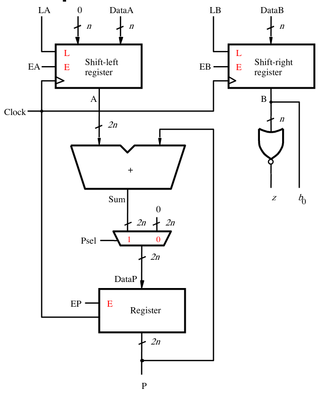
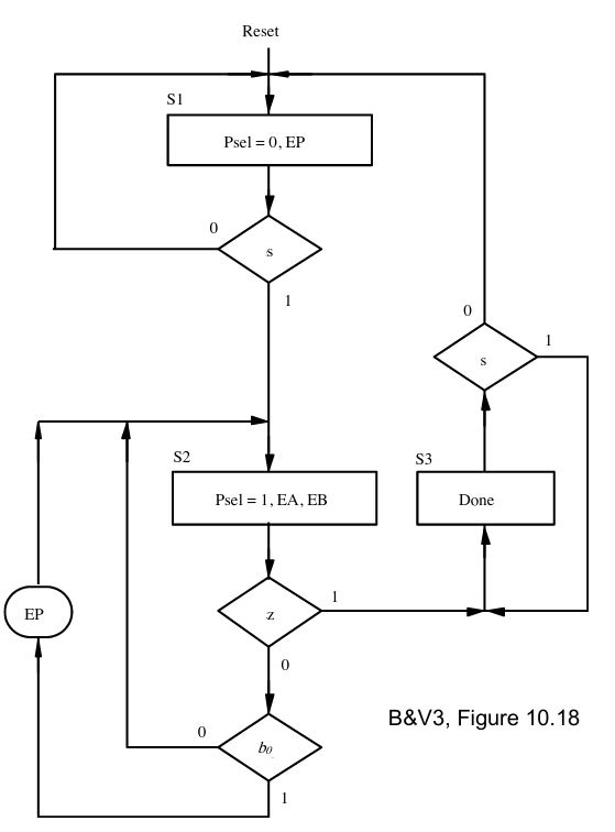
Multiplication Circuit
Slides: 08-Design.pdf

Division Circuit
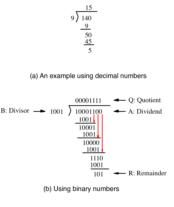
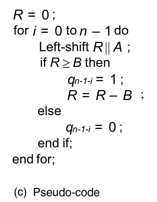
Left-shift R || A- Shift the MSB of A into R
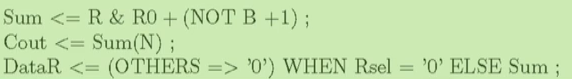
Enhanced Divisder Circuit
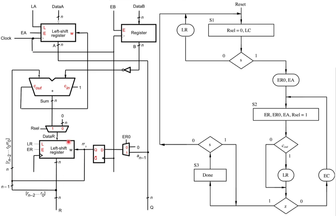
- Combine the Q and A register
- Flip-flop used
- Shift register holds both result and remainder
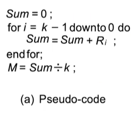
Mean of K