Timers
Contents
Binary counters that can be used to measure time periods/speed/frequency, generate PWM signals, schedule real-time tasks, etc…
- Timer 0 - 8-bit
- Timer 1 - 16-bit
- Timer 2 - 8-bit
- Timer 3 - 16-bit
- Timer 4 - 16-bit
- Timer 5 - 16-bit
Initialising the Timer
Can set the initial value of the counter to
- 0 - Controlled by a
reset - A number - Controlled by a
count signal
The direction of the counter can be controlled by a direction signal
Interfacing with the Timer
Writing control bits into TTCRnA and TTCRnB
Timers can output:
- Overflow interrupt request bit
- Output Compare interrupt request bit
OCnbit
Timer Interrupt Mask Register - TIMSK0
- Set
TOIE0to enable the Overflow Interrupt - Set
OCIE0A/OCIE0Bto enable the Compare Match Interrupt
Timer Interrupt Flag Register - TIFR0
OCF0A/OCF0Bis set when the corresponding interrupt is triggeredTOV0is set when an overflow occurs
These bits are cleared by hardware when the interrupt is handled.
They can be manually cleared by writing setting the bit to 0.
Timer Counter Control Register - TCCR0A and TCCR0B
(For timer 0)
COM0xn/WGM0n/FOC0- Mode of Operation
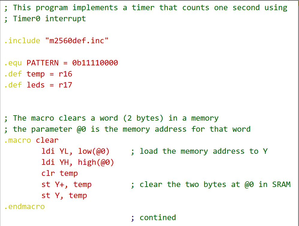
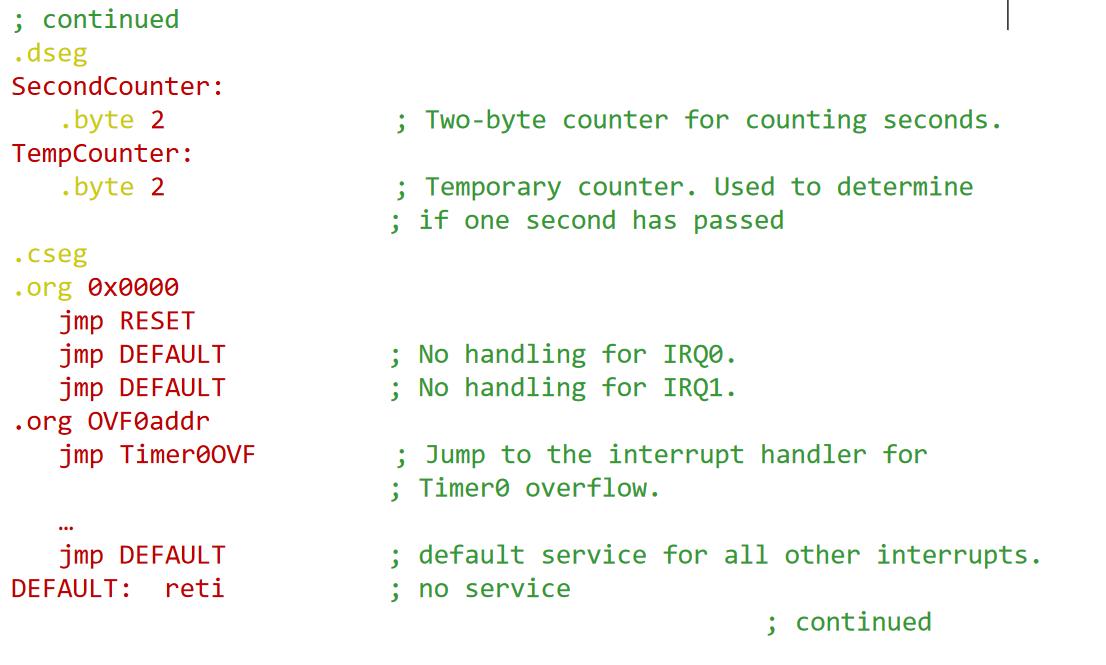
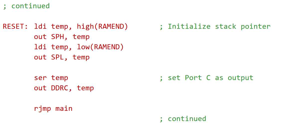
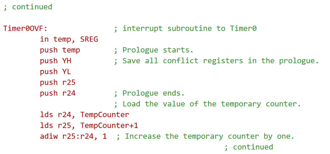
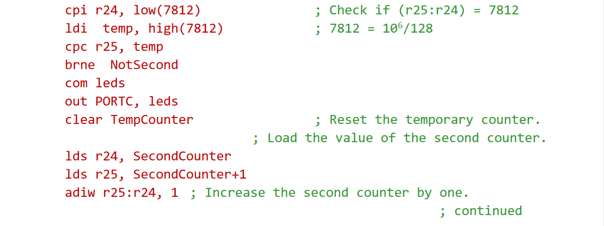
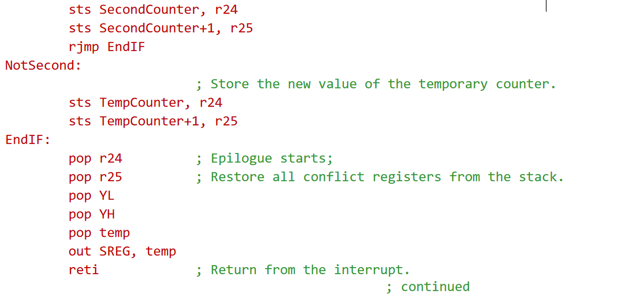
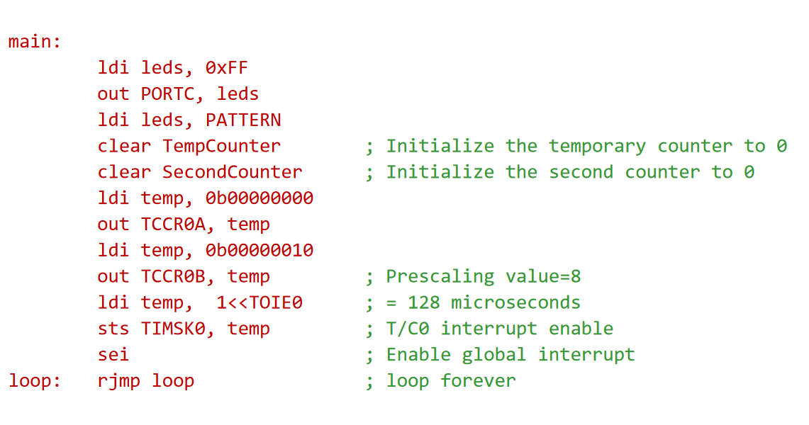
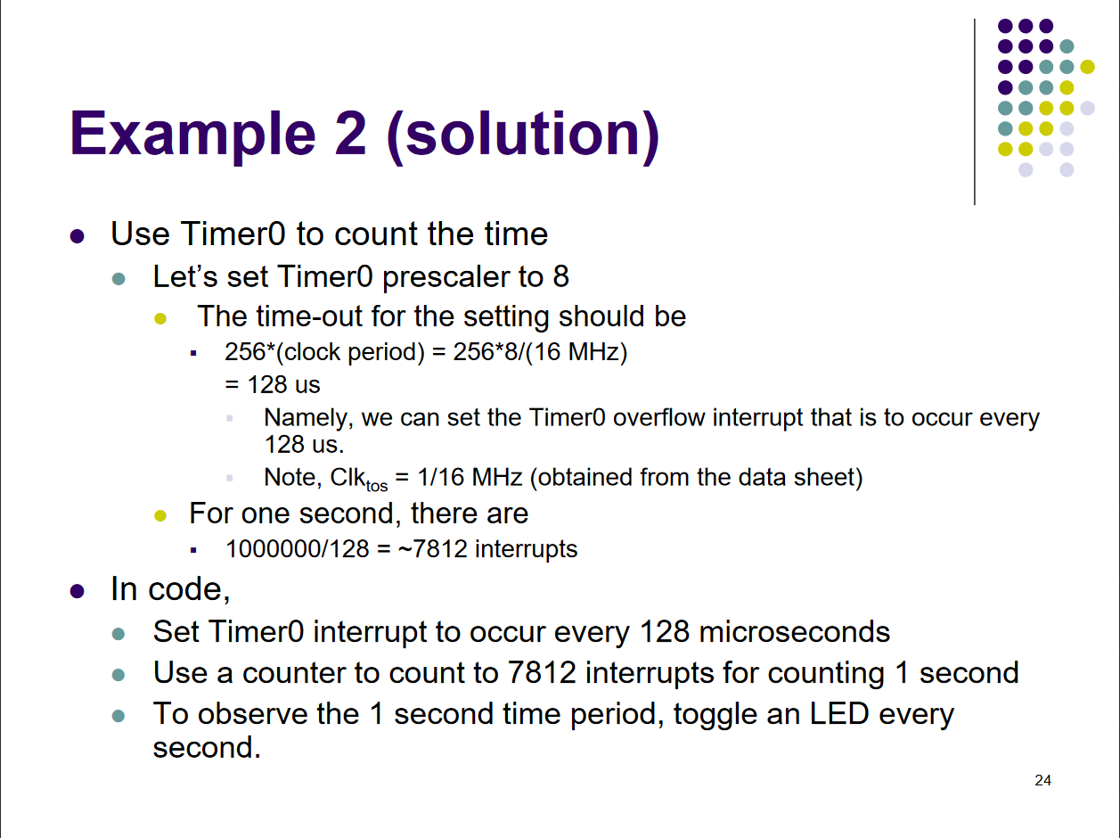
Example: 1 Second Timer
Code