Serial Devices
Contents
Parallel IO requires a wire for each bit, and may have synchronisation issues if not all of the bits are written nor read at the same time.
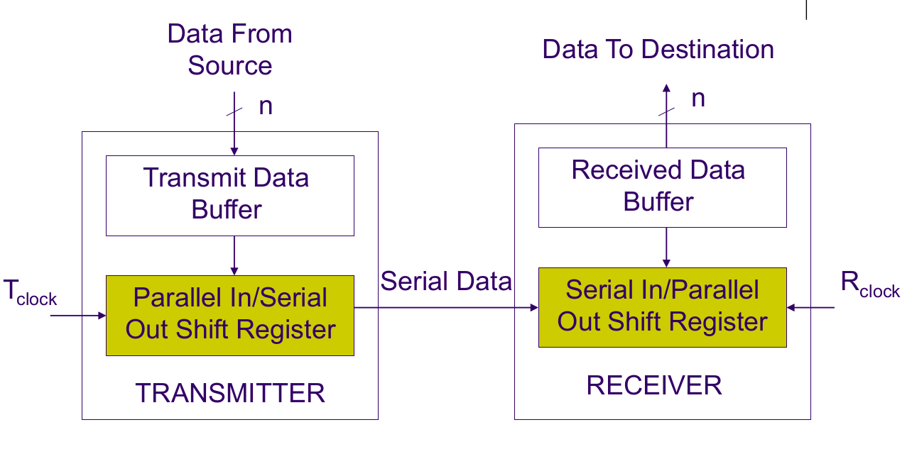
Data is loaded onto the Parallel In / Serial Out (PISO) register, and the T_clock (transmit) shifts the data bits out from the register to the receiver.
On the receiving end, the R_clock (receive clock) shifts the data bits out from the Serial In / Parallel Out (SIPO) register, and into the received data buffer where it can be access in parallel
Synchronous Serial
- Transmitter and receiver clocks are synchronised
- Requires extra hardware for clock synchronisation
- Allows faster data transfer rates
Asynchronous Serial
Triggers.
Universal Asynchronous Receiver and Transmitter (UART)
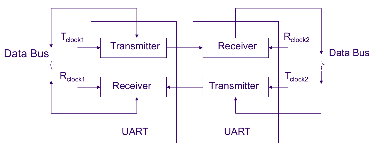
The UART circuit is both a transmitter and receiver in one.
The least significant bits are transmitted before the most significant bits.
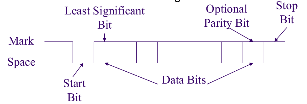
Encoded data is encapsulated with a start and stop bit.
When the receiver detects the start bit (space level for one bit-time), it begins the read clock.
When the receiver detects the stop bit, it stops the read clock.
Baud Rate
Rate of transfer of bits per second
Commonly 110, 150, 300, 600, 900, 1200, 2400, 4800, 9600, 14400, 19200, 38400, 57600, 115200, 230400, 460800, 921600.
Communication Systems
Simplex
Data is sent in one direction only.
Two wires needed
Half Duplex
Data can be sent in both ways, but in only one direction at a time.
Requires a handshaking system + hardware to share the same wire.
Full Duplex
Data can be sent in both ways, as each device has their own transmit wire (receive on the other end) Three wires are needed (but often called 4 wire systems as we often keep wires in pairs)
Communication Devices
- DCE - Data Communications Equipment - Provides a path for communication - i.e. Modem
- DTE - Data Termination Equipment - Connects to a communication line - i.e Computer
Modems
MODulator / DEModulator
- Modulator - Converts logical levels into tones to be sent over wire.
- Demodulator - Converts tones into logical levels
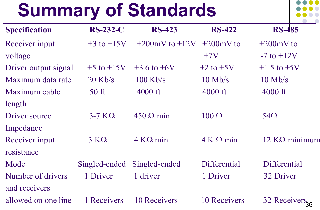
Serial Standards
Standards are important to allow for the communication between devices of different manufacturers.
For example RS-232-C, RS-422, RS-423 and RS-485.
Standards often involve the negotiation of
- Handshaking signals
- Direction of data flow
- Types of communication devices
- Connectors and interface mechanical consideration
- Electrical signal levels
RS-232-C is often used, however a standard like RS-422, RS-423 or RS-485 should be used for signals that need to be transmitted more than 15m, or faster than 20 Kbps.
Standards also have standardised pin connections - ie RS-232-C has DE9 and DB25 pins
AVR USART
In AVR, there are two USART (Universal Synchronous/Asynchronous Receiver/Transmitter) controllers.
Each can be configured for either synchronous or asynchronous communication.
They support many different serial protocols, and also support parity and error detection.
Interrupts
To communicate with the host controller, they offer three interrupts:
- RX Complete
- TX Complete
- TX Data Register Error
Components
- Clock Generator - Baud rate generator, slave clock input logic
- Transmitter - Single write buffer, serial shift register, parity generator, control logic
- Receiver - Receive buffer (UDR), serial shift register, parity checker, control logic, recovery unit (for async communication)
Frame Formats
Specification of how many / value of start bits, data bits, parity bits, parity type and stop bits
Parity Bit
Used to roughly check whether the received data has been corrupted during transmission
AVR Control Registers
UCSRA- Status flags
- Transmission speed
- Processor usage
UCSRB- Enabling interrupt, transmission operations
- Frame formats
- Bit extension
UCSRC- Operation configuration
Initialising USART on AVR
- Set the baud rate
- Set the frame rate
- Enable the transmitter (
TXENbit inUCSRB) / receiver (RXENbit inUCSRB) / both - [Optional] Enable the global interrupt flag (
sei)
Transmitting
Polling
- Wait for
UDREinUCSR1Ato be set (withlds->sbrs->rjmp) - Load data into
UDR1(withsts)
Interrupts
Wait for USART Data Register Empty (UDRE) or Transfer Complete (TXC) interrupt, then load next byte.
Receiving
Polling
- Wait for
RXC1inUCSR1Ato be set (withlds->sbrs->rjmp) - Load data from
UDR1(withlds)
Errors
Main from of errors come from out-of-sync data, and from signal noise.
Error Detection
- Checking for Frame error - Check if first stop bit is correctly received
- Checking for Parity error - Check if the number 1’s match the parity bit
- Checking for Data Overrun error - Check if data has not yet been read yet
Error Recovery (During asynchronous transmission)
In the AVR board, the recovery unit samples and low-passes each incoming bit, improving the noise immunity of bits during reception.
It will also try to synchronise its internal clock with the incoming asynchronous frames.
i.e. Check the same bit multiple times (ie 3 times) to ensure the read level is correct; use the majority