ADCs and DACs
Contents
DAC - Digital to Analogue
A parallel output interface connects the DAC to the CPU.
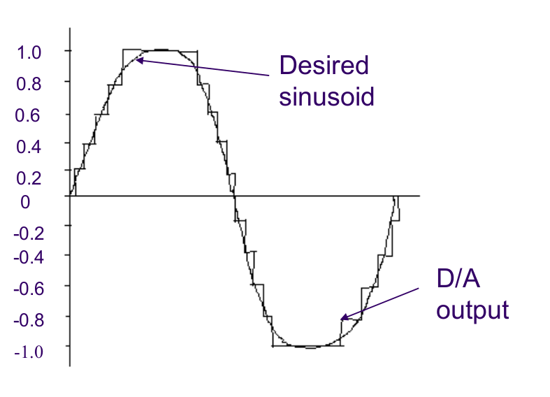
Digital values are converted in a continuous signal.
A signal conditioner circuit may be placed to smoothen the quanitized nature of the output.
It may also provide isolation, buffering and voltage amplification if needed
DAC Types
Binary Weighted DACs
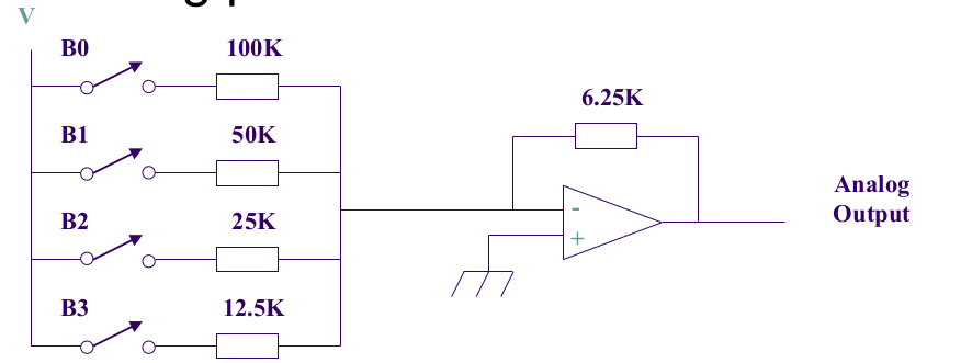
Each bit is connected to a different resistor - of weighted values.
As bits are toggled on, the combination of different active resistors are summed in the amplifier.
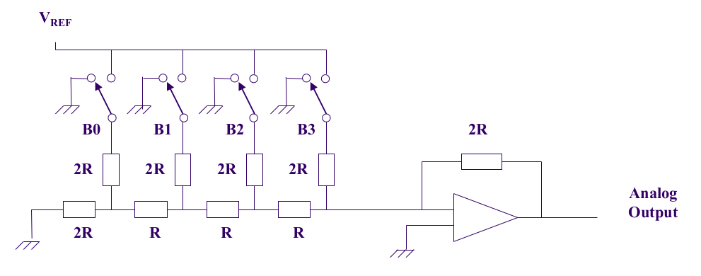
R-2R Ladder DAC
OMG ELEC2133
Resolution
The resolution is determined by the number of bits used for the smallest digital step.
Linearity
How close the output voltage aligns with the ideal value.
Settling Time
Time taken for the output voltage to settle within an error band (Usually +- 1⁄2 LSB)
Glitches
Glitches are caused when bit wires don’t change values at the same time as other values They can be eliminated using a sample-and-hold method - where a device holds the changing digital values for a period of time until all the bits have changed (i.e. capacitor and switch)
ADC - Analogue to Digital
Physical analogue -> [Transducer] -> Electronic analogue -> [Conditioner] -> Electronic analogue -> [(Optional) Multiplexer] -> [ADC] -> Electronic digital -> [Processor]
Transducer
Converts physical values (ie microphone membrane) into electrical signals (either voltage or current)
Signal Conditioner
- Isolation and buffering - Separate the transduced electronic analogue signal from the ADC (circuitry)
- Amplification - Increase the magnitude of the signal
- Bandwidth limiting - Apply a low-pass filter to remove high-frequency noise, so that there is a smaller range of values to digitize
Multiplexer
If multiple signals need to be done, it is done here before being passed to the ADC
Sampling
Claude Shannon’s Theorem - When a signal f(t) = X*sin(2*pi*f*t) is to be sampled (digitised), the minimum sampling frequency must be twice the frequency
- Nyquist rate - Minimum frequency that ensures that each period is accurately recorded, such that the full information is preserved
- Twice the maximum frequency of a signal
- Undersampling occurs when the sampling frequency is less than the Nyquist rate
- Aliasing occurs - where unwanted components appear in the reconstructed signal
ADC Types
SAR - Successive Approximate Register
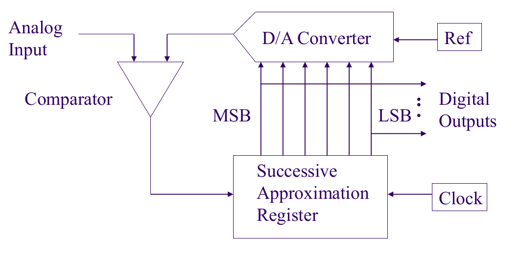
DAC operation works by comparing an input signal with a DAC in a comparator.
Each bit is tested from the MSB to the LSB.
As the first bit is enabled, the DAC will output a signal which is converted to the input signal.
Whilst the DAC signal is lower than that of the input signal, the next bit is also turned on.
Parallel ADC / Flash ADC
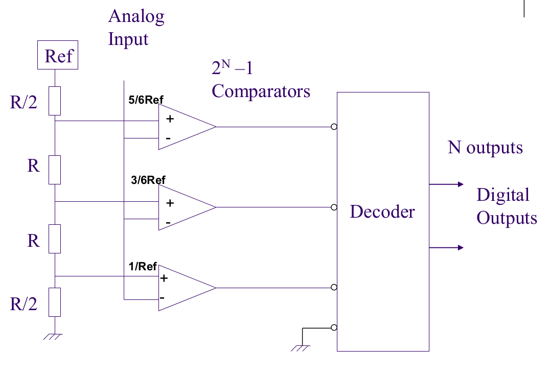
2^n - 1 comparators are used, each one comparing the input signal to a unique reference voltage.
Expensive - needs one comparator for every digital value.
Two Stage Parallel ADC
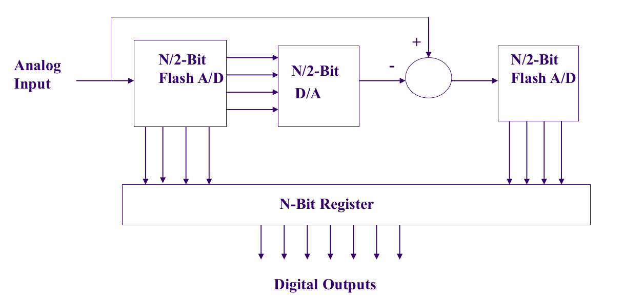
The MSB is calculated first, then the LSB is passed to a second set of comparators.
i.e. with an 8 bit, two stage parallel ADC with 4 bits first stage and 4 bits second stage2^(floor(n/2)+1) - 2 = 30 comparators vs 2^8 - 1 = 255 comparators.
Conversion Time
Time required to complete a conversion of the input signal, without aliasing.
f_max = 1/(2 * conversion time)conversion time = 1/2f
Resolution
The smallest analog signal which the converter will produce a digital code.
resolution = full-scale signal / 2^n
Accuracy
Closeness of the digital value to the analogue signal
Accuracy = 100% * V_resolution / V_signal
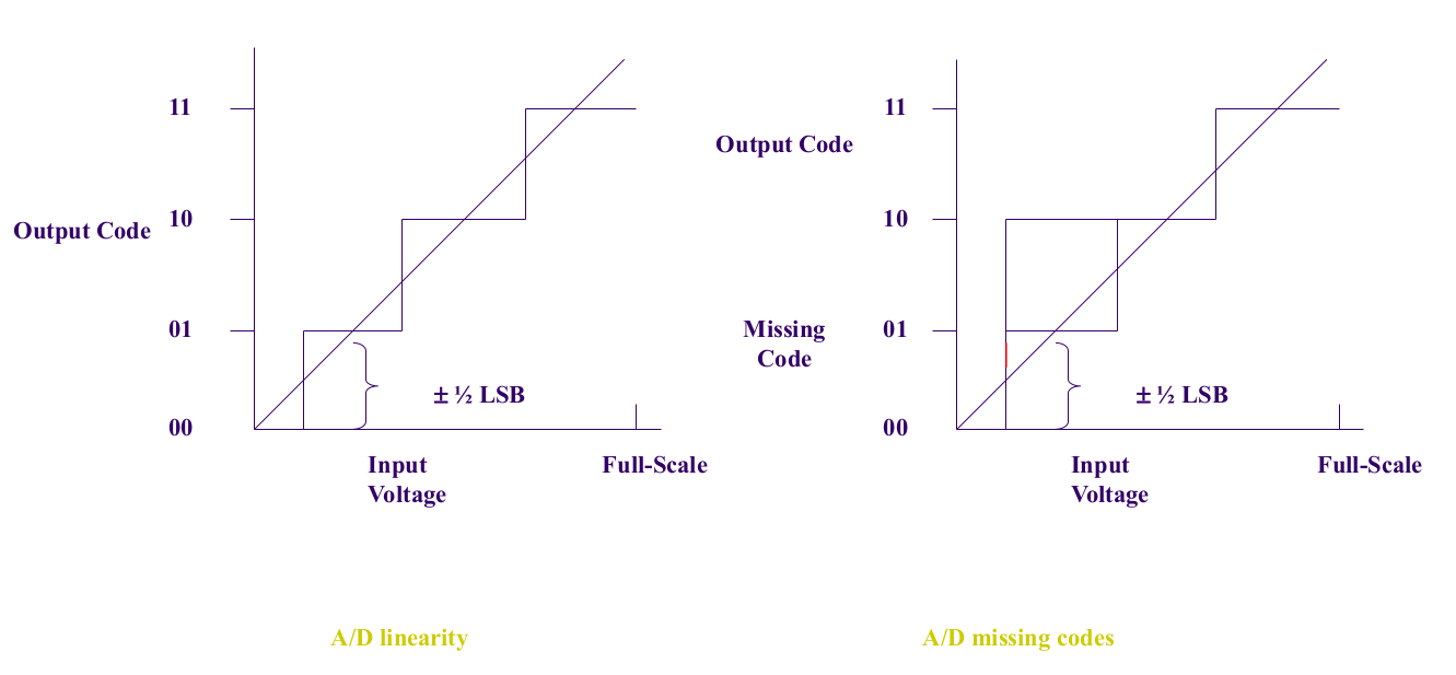
Linearity
How close the digital values are to their analogue signal values
- Best is +- 1⁄2 LSB
Missing Codes
Failure to output a digital signal given an analogue input
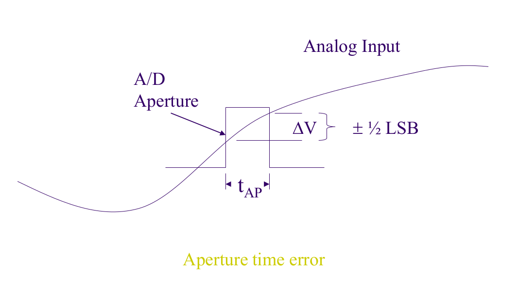
Aperture Time
Time it takes for the ADC to look at the input time.
Usually equal to the conversion time.
ADC Errors
- Noise - Induced noise in the analogue signal will produce digital conversion erorrs
- Aliasing - Sampling frequency too low
- Aperture - Signal variation during inspection
Solutions
- Noise
- Reduce noise
- Decrease the resolution (control the peak-peak noise)
- Aliasing
- Pick a better sampling frequency (f_good >= f_nyuist = 2x max frequency of input signal )
- Low-pass filter
- Aperture
- Aim to achieve
t_aperture = 1/(2*pi*f_max*2^n)
- Aim to achieve